Design and Research of Double Motor Individual Transmission Steel Bar Crimping Machine (1)
Shanxi Provincial General Machinery Factory Song Shouyi
The crimping machine is also called a sealing machine. It is the key equipment in the steel drum production line. At present, horizontal crimping machines for steel drum sealing at home and abroad can be roughly divided into two types, namely, single-motor centralized transmission and dual-motor single transmission. The single-motor centralized transmission is represented by the Italian General Machinery Company, and its products are very common in Western European countries. The KRUPP crimping machine introduced in Shanghai, China and the CARANDO crimping machine introduced by Harbin are of this type. The device is driven by a main drive motor to drive the spindles of the left and right headstocks respectively. The movement of the crimping roller is also driven by the motor via a cam mechanism (see Figure 1).

Figure 1 Single motor centralized transmission crimping machine
The dual motor is driven separately. Representative of LEIFELD. The equipment is driven by a motor to drive the spindles of the left and right headstocks. The crimping roller motion is hydraulically driven. In the West Germany barrel factory, this crimping machine is widely used. For many years, both of these crimping machines have been used in high-speed steel drum production lines abroad. Practice has proved that both types of crimping machines are successful. By careful comparison, the single-motor centralized transmission structure is complicated, the transmission links are many, the parts processing amount is large, the volume is large, and the weight is large. The dual-motor single-drive type simplifies the transmission link due to the dual-motor and hydraulic drive. The machining capacity of the parts is greatly reduced, the structure is simple, the volume is small, the weight is light, and the appearance is also beautiful.
After inspecting the barreling equipment in the UK, Italy and West Germany, we began to design the crimping machine. When selecting the equipment, it was decided to use the bilateral single transmission of the West German LEIFELD and the division as the model, and made some changes in combination with the specific conditions of China's industry. For example, the West Germany equipment hydraulic station uses a variable pump, the system is simple, the valve group is small, and according to our situation, only the quantitative pump can be used, the system is more complicated, and the types and quantity of valves are also many. West Germany adopts flange connection, and the main drive motor is installed at the rear of the left and right headstocks. The transmission is in the headstock and looks neat and beautiful. According to our situation, the motor can only be placed on the headstock, and the drive belt and clutch are mounted on the outside of the headstock. Although the maintenance is trouble-free, but the volume is increased, it is not as neat as the West Germany equipment. At that time, the electronic control part of West Germany LFIFELD company still used relay control. In Western Europe P. C has also been a little bit of a tool for barrel making. Taking into account the development trend of electronic control and P. The merits of C, we decided to adopt P. C control, the introduction of the United States. TI company's P. C. Practice has proved that this game is completely successful.
Here are some ideas and related technical issues when designing a dual-motor single-drive crimping machine. Talk about your own opinions:
First, the structure and composition of the dual-motor separate transmission crimping machine (see Figure 2)
The equipment mainly consists of a base, a left and right headstock box, a pressure roller device, a feeding device, a glue spraying and rubber heating device, a hydraulic station and an electric control part.

Figure 2 Dual motor separate drive crimping machine
1-hydraulic station; 2-pressure wheel device; 3-headstock; 4-base; 5-side guide; 6-loading device
The left and right headstocks have the same structural form, and each of the AC motors is driven by the primary belt and the first-stage spur gear, causing the spindle to rotate. The sealing disk is mounted on the end of the spindle. The left and right headstocks are pushed by the hydraulic cylinder to perform translational movement along the surface of the base rail to clamp and loosen the steel drum. The high-speed shaft end large pulley is equipped with an electromagnetic clutch brake on the outside, which ensures the clutch and brake of the main drive according to the rhythm of the loading and unloading.
Since the left and right headstocks are synchronously moved relatively, the barrel body does not generate axial movement when the sealing plates of the two ends clamp the bottom cover of the steel drum. After the sealing is completed, the left and right headstocks are retracted at the same time, and the steel drum can be smoothly disengaged from the two seals without any auxiliary mechanism.
The left and right headstock movements are driven by the respective feed cylinders. After the sealing disc is clamped to the steel drum, the process requires the system to maintain a certain pressure. This has been considered in the design of the hydraulic system, thus eliminating the need for a large mechanical tightening mechanism on this device.
Due to the simplification of the drive link, the volume and weight of the headstock are reduced.
This type of crimping machine has the characteristics of simple structure, novel structure and beautiful appearance.
Second, the dual motor single drive type crimping machine two motor load distribution and the synchronization of the two spindle revolutions
Many users have raised such a question: If the number of rotations of the two main drive motors is different when crimping, what will happen to the barrel? In fact, this problem does not exist. We know that when the left and right headstock sealing discs clamp the barrel, because the sealing disc is tightly attached to the bottom cover of the steel drum, and has a certain topping force, considering the rigidity of the barrel, It can be considered that the two sets of transmissions in the left and right headstocks are rigidly coupled together by the barrel. This situation is similar to the hard shaft coupling of two AC motors of the same model.
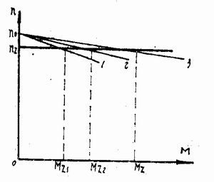
At this time, if the mechanical characteristics of the two motors are identical, the load is evenly distributed between the two motors, and the capability of each motor will be fully utilized. However, in general, even if two motors of the same type are used, it is impossible to have the same motor characteristics due to manufacturing reasons. Fig. 3 shows the characteristic curves of the hard shafts of two AC motors with different characteristics. The curves 1 and 2 represent the mechanical characteristics of the motors D1 and D2, respectively, and the curve 3 is the combined characteristics of the double motor drag. As can be seen from the figure, after loading, the number of revolutions of both motors becomes n2. At this time, the load torque is Mz, Mz=Mz1+Mz2 and Mz2>Mz1, that is, the load torque Mz is not evenly distributed to two. On the motor. The mechanically hard D2 bears a load greater than the characteristic soft D1. If the motor characteristics are too different, continuous use will cause one of the two motors to overheat, and the other will be under-loaded, not fully utilized, and the load distribution will be uneven, resulting in inconsistent wear of the two sets of transmission systems. In theory, in order to make the load as close as possible to the average distribution between the two motors, the characteristic curve of the two transmission motors should be as close as possible. When the motor is ordered, the motor manufacturer can request and filter the characteristic curve. We measured the load condition of the two motors under the condition of steel drum crimping, and the uneven distribution of the load was not serious. Especially for some famous brand manufacturers, it is not necessary to screen the characteristic curve. By the way, after using the device for a period of time, you may wish to pay attention to the wear of the two transmission links. If there is a significant difference, the positions of the drive motors can be interchanged, so that the load on both sides can be balanced to ensure uniform wear on both sides of the drive.

Figure 3 Mechanical characteristics of hard-shaft coupling of double AC motors
Third, the advantages of hydraulic drive crimping wheel
The single-motor centralized transmission type crimping machine and the movement of the crimping pressure roller are powered by the main motor, and the cam mechanism is driven by the transmission device to push the pressure roller for the feeding motion. The basis for using this transmission method abroad is that the barrel factory only uses cold-rolled plates and fully automatic seam welders. We know that cold-rolled sheets have much better plate and plate thickness tolerances than hot-rolled sheets, while fully automatic seam welders have a weld edge width of only 2.2-2.4 mm, and the thickness of the edge is only about the thickness of the base material. 0.lOmm. When crimping, the weld will not cause sudden spikes due to "ultra-thickness". Because the product is single, the process is mature, and there is a suitable cam curve, there is no need to adjust the speed in the work. This “pure†and “net†process from raw material to finished product ensures that the equipment can satisfactorily produce high quality steel drums on high-speed barrel production lines. On the contrary, the situation of the current barrel factory in China is far from the same. There are probably more than 300 manufacturers of barrels in the country, all of which use cold-rolled sheets to produce steel drums. The manufacturers of fully automatic seam welders with cold-rolled sheets and imported ones are even rarer. The hot-rolled plate with semi-automatic seam welding machine is the current status of domestic barrel factories. Under this circumstance, it is necessary to process the high-quality steel drums that meet the requirements of the International Maritime Safety Regulations Class I, which is the work we must carry out. The design of the dual-motor separate transmission crimping machine mainly considers these premise. condition.
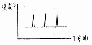
The national standard stipulates that the allowable deviation of the thickness of the hot-rolled steel plate is ±0.11 mm. That is, the thickness of the nominal size of 1.25 mm, the upper limit is allowed to be 1.36 mm, and the lower limit is 1.14 mm. Due to the backwardness of the rolling process and equipment of steel mills, the thickness of steel plates often exceeds 1.4 mm. When we debug the equipment for the user, we encountered the plate thickness of 1.43~1.47mm and the partial reach of 1.5mm. The weld lap width is about 10mm, and the lap thickness is about 1.8-2mm, or even 2mm or more. The seven-layer crimp of the seam weld can be over 2mm thicker than other parts. At this time, if the cam drive pressure roller is used, it is bound to cause an excessive "overpressure" at the super-thickness to produce a prominent peak load. This peak load is often several times the normal load value (see Figure 4). “Overpressure†means that the equipment is easily damaged, and it is easy to increase the leakage of the steel drum. In severe cases, the barrel board can be fractured. When adjusting the stroke of the pressure roller, the weld is thickened excessively, and other parts are not pressed.

Figure 4 Load diagram of cam electric pressure roller when holding pressure
Conversely, the dual-motor single-transmission crimping machine uses a hydraulically driven pressure roller, and the pressure and speed of the pressure roller can be adjusted within a wide range according to the crimping process. This is easy to meet the production of five-layer flat or seven-layer round-side steel drums, and is also suitable for pressing steel drums of different specifications or different thicknesses. After the working pressure of the pressure roller is set, the pressure difference between the upper and lower chambers of the cylinder that drives the pressure roller changes correspondingly with the load change of the crimping process, that is, the pressure of the upper chamber of the cylinder is set value, and the pressure of the lower chamber gradually increases with the load. Reduced. During this follow-up process, the pressure and load are always balanced, and the maximum pressure value should not exceed the set value of the system.
That is, P3=P1-P2
P3 - load force during the crimping process
P1 - N cylinder upper chamber piston force
P2——Cylinder lower chamber piston force
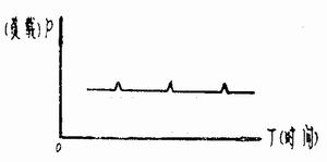
When the pressure is maintained, the mechanical limit of the tail of the driving cylinder acts, and the piston no longer moves downward, and the P2 value is reduced to the minimum. When the weld bead is pressed against the pressure roller, the piston is reversely moved due to the extra thickness. That is to say, the sum of P3 and P2 is slightly larger than P1 at this moment, and the hydraulic oil pushing the upper chamber by the upwardly moving piston is discharged into the tank from the overflow valve port. It returns to normal after passing through the weld. There is only a slight fluctuation in the pressure due to this process (see Figure 5). Therefore, there is no need for strict control of the pressure holding time of the two pressure rollers. We have established the crimping process to keep the sealing plate only for 3 weeks when the pressure is maintained, but some users keep the sealing disk for 12 weeks when the pressure is maintained. Since there is no "overpressure" problem, neither the steel drum nor the equipment will be damaged. This self-protection ability is not available in the cam drive. We have measured the force energy parameters under the load state of the crimping machine. The results show that the maximum pressure required to press the triple seven-layer round crimp on the crimping machine of the hydraulic drive pressure roller is only the cam mechanism drive roller. One-third of the impact load when pressing five layers of flat edges. The reduction of the force energy parameter reduces the size of the transmission shaft, the modulus of the transmission gear, the type of the bearing, the size of the headstock, and the like, and the size of the components related to the force energy parameters are correspondingly reduced, thereby greatly reducing the weight of the equipment.

Figure 5 Load diagram of the hydraulic drive pressure roller when it is under pressure
Makeup Brush,Retractable Brush,Hair Makeup Brush Set,Squirrel Hair Makeup Brush Set
SAMINA FORAM (SHENZHEN) CO., LIMITED. , https://www.saminabrush.com