Exploration on the Process of Conical Bucket Body Expansion Cone
Xin Qiaojuan
The author once talked about the bulging principle and bulging method of the barrel body in "The Theory and Practice of Steel Barrel Bulging Technology". With the rapid development of the petrochemical industry and the flourishing of foreign trade, the requirements for its packaging containers are also coming. The higher. It not only requires convenient and reliable transportation, but also requires beautiful and beautiful. To this end, a conical bucket (convenient bucket) came into being. However, the barrel of the cone barrel is unfolded in a fan shape. If the sheet is cut in a fan shape, the mold is complicated and vulnerable, and the punching equipment is large, which is not conducive to mass production, so the expansion cone method is often used. The utility model is characterized in that: when the material is cut, the diameter of the conical small head is unfolded, and the rectangular strip is cut into a cylindrical barrel body, and then the barrel body is sleeved on a dilating cone mold, and is expanded once on the hydraulic machine.
This method is only suitable for low carbon steel sheets with an elongation of more than 20%. When cutting, pay attention to the rolling direction of the steel plate so that the stretching direction and the rolling direction are the same, which can prevent cracking and reduce waste.
When welding the barrel, if ordinary seam welding is used, the overlap width is 8 to 10 times of the plate thickness, the shear strength at the weld is not a problem, and the fracture phenomenon does not occur here during the stretching. Occasionally, cracking occurs in production practice due to improper solder cooling rate. This is an accidental factor and is easy to handle and eliminate.
The advanced seam welder has greatly improved the precision of the weldment due to the precise work fixture. At present, the lap width of the weld can be reduced to 1-2 times the thickness of the plate, and the high temperature and high pressure have made the welding close to the butt joint, and the weld is only subjected to tensile stress. Since no coolant is added, the metal is slowly cooled and the crystal grains are coarse; the hardness is low and the toughness is good, so there is no stretching. The possibility of breaking.
-, the principle of the expansion cone process
The cylindrical barrel body is plastically deformed by the internal pressure P0, and the grain of the barrel metal is elongated and thinned in the circumferential direction, and the stress is maintained at the yield point. At this time, the metal deformation does not exceed the fracture limit, and after the external force is removed, permanent deformation is left.
Second, the pressure in the process of the expansion cone
The drum body is cut along its axial direction, and the length of the semi-circular barrel is taken as the research object. The pressure acting on the inner surface of the semi-circular barrel is P0, and the resultant force is N (Fig. 1):
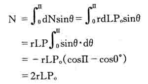
Ie N=DLP0
Where: barrel radius r = (inner radius + outer radius) / 2
Bucket diameter D=(inner diameter + outer diameter)/2
The balance with the resultant force N is the internal force T acting on the longitudinal section of the barrel wall. The value should be:
T = 2SLδ ring
Where: S is a wall thickness, obviously N=T, so DLP0 = 2Sδ ring
Then P0=2Sδ ring/D
It can be seen from the formula that P0 is inversely proportional to D. Obviously, the delta ring should be taken as the yield limit δs of the material. Δs can be found in the manual according to the nature of the material.
If δ ring = δs is taken, the minimum pressure P0 required for the bulging cone can be calculated.
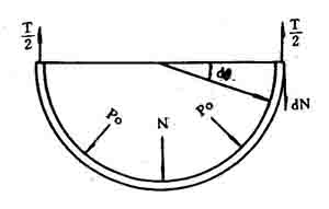
Figure 1 Stress calculation
Third, mold design and parameters
The mold construction is shown in Figures 2 and 3.
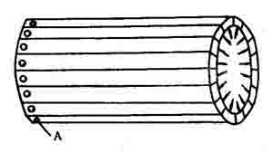
Figure 2 Schematic diagram of the expansion cone mold
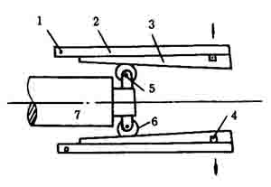
1-fixed axis A; 2-valve; 3-valve ramp; 4-tension spring; 5-small shaft; 6-small roller; 7-slider.
Figure 3 Schematic diagram of the expansion cone mold structure
The bulging cone mold is composed of a 16-valve flap, one end of which is rotatable about a fixed axis Ao. The 16-valve flap fits into a cylinder with an outer diameter slightly smaller than the working inner diameter. The inner diameter of the mold becomes a cone. When the slider B is pushed forward, the flap opens and the barrel is swollen out of the taper. When B is retracted, the flap returns to its original shape under the action of the spring force, and the workpiece is taken out.
The bottom of the barrel is D1 in diameter, the upper part is D2 in diameter, the height is L, the material is low carbon steel, the yield strength is δs, the elongation is δ, and the taper of the mold is tgα, which is divided into n flaps.
The minimum pressure at the time of bulging is
P0=2Sδs/D1
Where D1 is the bottom diameter; S-plate thickness.
When the outer circle of the mold is divided into n petals, the arc length AB of each valve is:
AB=π·
The tension that should be applied to each flap is:
N1= AB·L·P
Where L-barrel is high.
When the slider advances, the axial force of each flap is f, then
F = N1tgα ten N1f0
Α-lobed bevel angle
Tgα-slope
F0-friction coefficient, take f0=0.15
The total thrust is: F = Σf = nf
in conclusion:
1. The amount of deformation cannot be increased indefinitely, that is, the ratio of the tapered head cannot exceed the elongation of the material, otherwise fracture will occur. Therefore, the calculation of the elongation is required.
2, the weld will generally not break, because the width of the edge is about 4mm. Welds generally do not need to be checked and cracks appear. The reason should be found from the seam welding specifications and materials.
3. It is best to use rolling friction between the slider B and the bevel of the flap to prevent wear. At this time, the strength check of the small shaft should be performed. In addition, the friction surface should be well heat treated and lubricated.
Fourth, molding equipment
1. Semi-automatic barrel bulging machine
The hydraulic system of the semi-automatic barrel bulging machine is shown in Figure 4. The oil pump is started. After the working oil is sucked from the fuel tank into the high and low pressure pumps, it enters the main valve body. After mixing in the valve body, it enters the electro-hydraulic reversing valve and then enters the working cylinder. The push piston descends rapidly, and the inner cone of the mold pushes the valve outward to expand. After the valve contacts the iron sheet, the resistance increases, the high pressure pump supplies oil separately, the working pressure increases, the cylinder is inflated, and the piston continues to descend to the specified position. When the stroke stop is touched, the resistance increases, the working oil pressure rises sharply, the pressure relay 9 works, the electro-hydraulic reversing valve 11 works, the electro-hydraulic valve reverses, the piston rises, the expansion cone mold contracts, the piston reaches the apex, the oil pressure Increase, the pressure relay 10 works, so that the oil pump stops supplying oil, and one working stroke is completed.
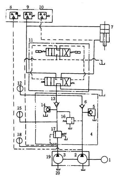
Figure 4 Hydraulic system diagram of semi-automatic barrel bulging machine
When the semi-automatic expansion cone machine is used in the above system diagram, the working cylinder and the expansion cone mold can be placed horizontally as shown in Fig. 5.
This structure swells one workpiece per working cycle and can produce 400 to 600 workpieces per hour.
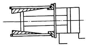
Figure 5 Schematic diagram of semi-automatic expansion cone machine
2, automatic expansion cone machine
The automatic expansion cone machine can be used on the entire automatic production line or can be used separately.
Its working principle and oil circuit are basically the same as the above semi-automatic hydraulic expansion cone machine (Figure 6). Only one feed cylinder 1 is added, and accordingly an electrohydraulic directional control valve 6, as well as a pressure relay 4 and an electrohydraulic directional control valve 5, are added.
The working process is as follows: the motor is started, the electro-hydraulic reversing valve 5 is operated, the cylinder 1 is supplied with oil, the piston is raised, and the workpiece placed on the tray 2 is pushed into the outside of the dilating cone mold, and the piston is pushed to the predetermined position and then killed. The pressure rises, the pressure relay 4 works, the electro-hydraulic reversing valve 7 works, the working cylinder 3 enters the oil, the piston descends, the expansion cone mold starts to work, the workpiece is inflated, the piston is lowered to a fixed position, the oil pressure rises, The pressure relay works to make the electro-hydraulic reversal, and the two pistons of the upper and lower cylinders are simultaneously retracted, and one working cycle is completed, waiting for the start of the next cycle.
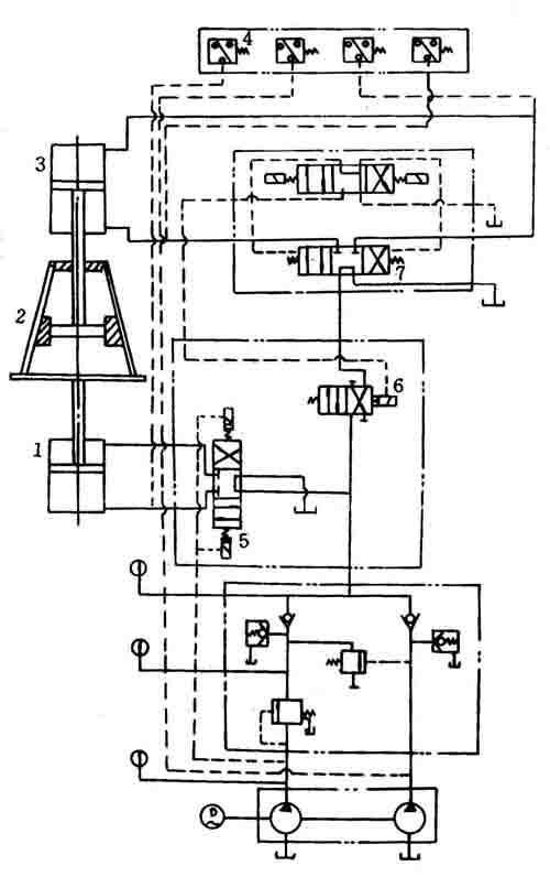
Figure 6 Hydraulic schematic diagram of automatic expansion cone machine
Baby High Chair,Baby Safety Chair,High Chair For Baby,Baby Table Chair
Zhejiang Lamon Technology Inc. , https://www.babychaires.com